If You're Reading This... Thank ASCII
Please Log In for full access to the web site.
Note that this link will take you to an external site (https://shimmer.mit.edu) to authenticate, and then you will be redirected back to this page.
This lab has 2 checkoffs. Make sure you complete them and upload your code at the end for full credit.
1) Attendance
Make sure to scan a QR code from the front and then sign in. You must sign in before proceeding (so resolve any WiFi-related issues now before moving on).

2) ASCII Encoding
On this webpage in front of you there's a lot of text, and this text is made up of individual characters (letters, numbers, symbols, spaces, etc). However, as we've discussed, computers don't directly use these character symbols, they work with bits. So there needs to be some sort of standardized way for a character to be encoded using 0's and 1's. Not sure what the current state of the world would be if there wasn't. Feel free to speculate (but not for too long, we've got work to do).ASCII (American Standard Code for Information Interchange) is an encoding we can use (and that is used extensively today, even within more complex character-encoding schemes such as Unicode1) to convert between characters and bits. ASCII encodes 128 characters, so, remembering that \log_2(128) = 7 (or that 128 = 2^7), ASCII encodes each character as a 7-bit unsigned integer value. This conveniently fits into a byte (in this lab, we'll just set the most significant bit to 0).
The mapping is as follows:
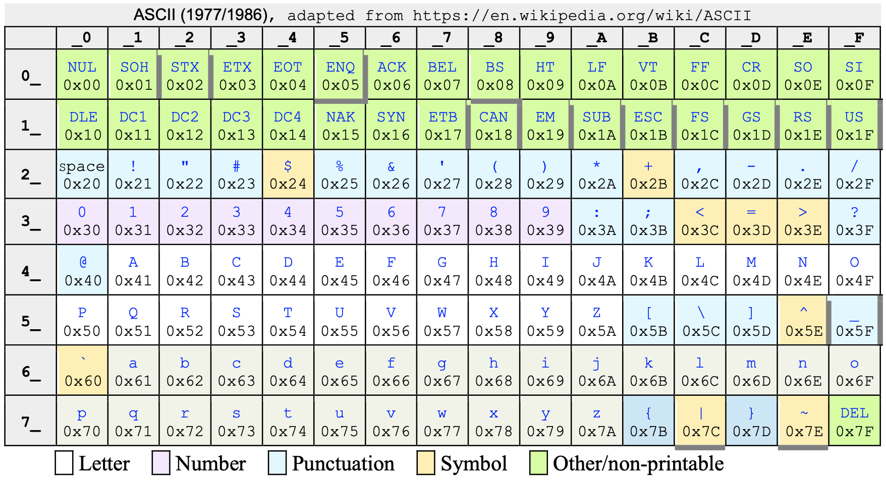
Answer these questions to become familiar with the mapping.
3) Hardware Setup
Our hardware setup today is very similar to that of our Hit the Bit game in postlab 1, so if you still have that set up, great!
Here's a diagram of the circuit we'll be using today.

If you have everything set up from the postlab, you only need to make two changes: (1) disconnect the SW7 to ESP32 pin 9 wire, and (2) connect BTNF on the PCB to pin 9 on the ESP32.
4) Software Setup
4.1) Starter Code
Download the starter code for today's lab here: [Starter Code]. There will be two (2) files in the src folder:
main.c, your main C file. This file is our "entry point", a file that contains a function which the system will "start" from.ascii.hA header file containing data corresponding to an 8x8 rendering for each ASCII character.
Extract the contents of the zip (by right clicking and choosing extract on windows or linux, or by double clicking on the .zip file on a Mac): Move this extracted 6190_lab2 folder into the 6190 folder you created last week (or whatever folder you've chosen to keep this class's labs and postlabs in).
In addition to the starter code from the website, please copy over 6190.h from postlab 1 into the src folder for lab2.
As a reminder, 6190.h is the header file that contains definitions of constants and functions specific to our hardware setup.
Verify that main.c, 6190.h, and ascii.h are all in your project's src folder. Before proceeding with lab2, make sure that you've reactivated your 61903_python virtual environment.
#include "ascii.h" at the top of your 6190.h file, on line 3.You can (and probably should) use any functions implemented in 6190.h throughout this lab. Additionally, you are not allowed to import any additional libraries, including string.h.
4.1.1) Timing is Key
Take note of these lines of code at the bottom of your main while loop:
// Code to slow down loop so that "bouncing" associated with a single button press doesn't
// look like more than one button press. Write all of your code in above this point in the loop.
int start = millis();           // Get "start" time stamp
while(millis() - start < 50);   // Wait until current time stamp - "start" is greater than 50ms
These essentially make your loop execute at a certain rate. In our case, we will be detecting a button push later on in the lab, and this will slow down our loop so that any noise associated with the button push isn't detected as individual pushes. We're just calling this out now because you shouldn't delete them.
4.1.2) Setup
We went ahead and put all of our setup-related code into a single setup() function that is defined and implemented in main.c.
For some context, setup() is configuring various things. It calls:
timerSetup()in order to initialize one of the timers on the ESP32.setupDisplay()to setup the display as we did in postlab 1.eraseBuffer()anddrawBuffer()to have the LED array start out blank.pinSetup()to set up all of the switches and buttons needed for the lab.
You can find all of these functions in 6190.h in case you are interested in their implementations (though you were the one who wrote pinSetup()).
Don't delete any of this -- otherwise things will not work (as expected, or at all).
5) 'C' 'h' 'a' 'r' 'a' 'c' 't' 'e' 'r' 's'
We'll first introduce the idea of inputting characters to our system by dealing with them individually. We would like to start by having our system continuously print out a character to the serial monitor based on the state of the 7 switches.5.1) Interpreting Switches as an Integer
In the first portion of this lab, we are going to write a program that will take a 7-bit binary value as an input (from the switches) and output the corresponding ASCII character on the serial monitor.
- Note that, by convention,
SW0will be the least significant bit andSW6should be the most signficant bit. This goes along with how we read binary numbers, with the rightmost bit being least significant.
Our first step will be to write a helper function, switchToBinary(), (you can see its definition in main.c) that will convert these 7 switch inputs to an unsigned 8-bit integer value, or a char.
switchToBinary() takes in no arguments and should:
- convert the 7 switch inputs to an unsigned 8-bit binary number, then
- return that unsigned 8-bit value.
Note that the most significant bit in the value will not come from a switch, and it must be zero to comply with ASCII encoding.
Please complete switchToBinary() below.
- Any functions or constants from
6190.hthat you would need to implementswitchToBinaryare available for you to use. - You may find the array
switch_pins(which is defined for you) helpful. You can see it toward the top ofmain.c, and we have provided it for reference below:
int switch_pins[8] = {SW0, SW1, SW2, SW3, SW4, SW5, SW6, SW7};
- Note that you will need to read the values of these pins using
pinRead().
Once that's working, copy your implementation into the definition of switchToBinary() in main.c.
Take note of these lines in the starter code (in app_main()), and make sure you understand what they're doing.
ascii_input = switchToBinary();
printf("Integer value: 0x%x, ", ascii_input);   // printing this value using %x formatter gives a hexadecimal value...
printf("ASCII character: %c\n", ascii_input);   // ... printing the same value with %c formatter gives a character
Now re-compile your code by doing llp-bc compile ./, and then upload your program to the board using llp-bc flash ./. Once it's uploaded, open the Serial Monitor using llp-bc monitor. You should see some stuff printing out like:
Integer value: 0x40, ASCII character: @
Integer value: 0x40, ASCII character: @
Integer value: 0x40, ASCII character: @
Integer value: 0x40, ASCII character: @
As you mess with the switches, the integer value and corresponding ASCII character should change.
5.2) Adding a Button
Now, we want a button press to control these printf statements. Specifically, when BTNF is pressed, we want to print out the integer value and ASCII character just once. Then, nothing should print out until BTNF is released and pressed again.
5.2.1) Levels vs. Edges
Find these lines in the starter code:
int btnf = pinRead(BTNF);        // read BTNF to obtain the current state of the button
if (btnf == 0){
  /* TO-DO: Put your print statements from the last part in here */
}
Uncomment them, then move the print statements from the last part to be inside this if statement (so that they would only print out when btnf == 0).
Re-compile, upload your program to the board, and open the serial monitor. Nothing should be printing out. Press BTNF, and you'll notice that a few lines (or more, depending on how long you held it down) have printed out. This isn't exactly the behavior that we want. Let's think about what's going on.
In Lab 1, we learned that the digital value of a GPIO pin connected to a button will be 0 when a button is pressed and 1 when a button is not being pressed.2 In our program, we use the pinRead() function to read the value of this GPIO pin once during each iteration of our main while loop (which occurs every 50ms). So, our program samples this value just once every 50ms. This is illustrated in the figure below.
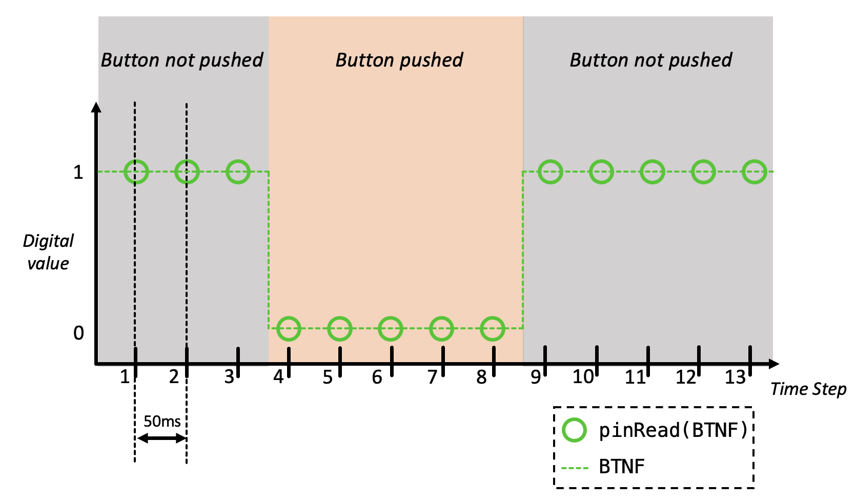
Our current program is detecting the level of BTNF, meaning that it is printing based on just the current value (or level) of BTNF. Specifically, it prints whenever BTNF is being pressed (or btnf == 0). This means, if the state of BTNF was as in the figure above, lines would print during time steps 4, 5, 6, 7, and 8 -- even though the button was pressed only once!
We want only a single line to print whenever we press BTNF. This means that the two print statements should only execute one time when we push the button (even if we hold the button down). In order to execute these print statements only once, we must introduce the idea of state. Sometimes, a program's behavior depends on what has happened in the past (in addition to what is currently happening). We detect a new button press by comparing the previous value of BTNF with the current one. Specifically, we are looking for a change in its (digital) value, or an edge.
5.2.2) Your Turn
Let's implement this behavior. Update your program so that just one line prints out each time you press the button (even if you hold the button down). You may find the chart above helpful. Note that this behavior can be implemented by adding/modifying just 3 lines of code.
Once you have updated the program, upload it to the board.
BTNF and hold it down. Only one line should have printed out. Release BTNF, nothing should be printing still. Press BTNF again. Another line should print out.
6) "Characters"
Single characters usually have little meaning to us; communication mainly happens using words, phrases, and sentences, which (for the most part) involve more than one character. When programming, these multi-character data structures are called strings. A string is stored in memory as an array of characters, which is known as a char array.
6.1) Null-terminated Strings
Strings in C end with a null-terminating character '\0' (its integer value is 0). Oftentimes a computer program, when prompted to work with a given string, will start at the base address of the char array and interpret the values at consecutive addresses as being characters in the current string. When it encounters the null character, it knows that's the end of the string. If there is no null character, the program could continue on into parts of memory that have nothing to do with the string (and that's not good!).
Now, we are going to use our switches and button inputs to build up a char array. Once the string is complete (as indicated by the null terminator being added to the char array), our system will then print the string on a new line on our serial monitor.
In liteXL (or editor of choice) (in your main.c file), modify your program so that:
- On a button push, add one character (which is indicated by the seven switch inputs) to a char array without overwriting any of the previously-entered characters in the current string.
- If the entered character was the null-terminating character (
'\0').- (1) print the string using
printf(). For readibility, make sure to print it on a new line! - (2) The character entered after this should start a new message.
- (1) print the string using
- The char array should be able to store messages that contain up to 100 characters (and no more than 100 characters).
- You should use the same char array for every string. So, we should be using the same section of memory when building up each new char array.
On Windows (and maybe other machines) you'll really want to have a '\n' at the end of your print statements otherwise your message may be queued but not sent!
Once you have something you think might work, test it by trying it out on your board (re-compile, flash, and monitor)!
Demonstrate your working system (it should be able to correctly handle a random message from a staff member).
7) Rendering Characters
Now we understand how characters are encoded so that computers can receive, use, and transmit them. However, the ASCII encoding of a given character doesn't provide any information about how this character would be displayed on a screen.On an 8x8 grid, a 'B' would look something like this (it could vary slightly depending on font):
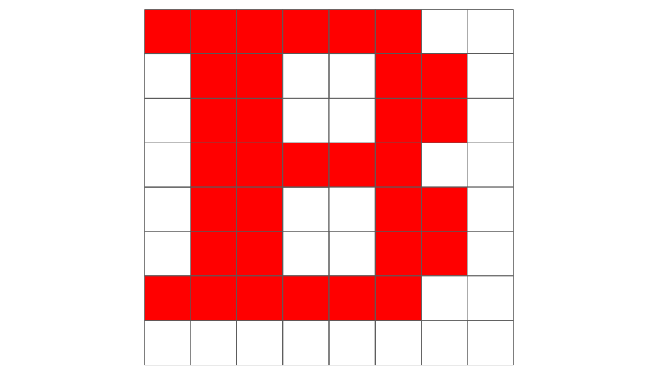
How can this information be represented in binary? An LED can be either on or off, which lends itself well to digital/binary values, since a 1 could correspond to the LED being on and a 0 could correspond to the LED being off. However, it would be very tedious to actually determine what numerical values to use in order to render each visible ASCII character. The good news is that someone else has already done this work for us.
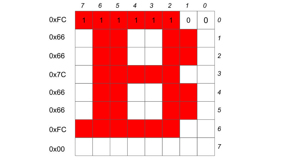
All of this information is defined in ascii.h, which was included in the starter code for this lab. ascii.h contains a 128x8 array ascii. Each of the 128 characters has an 8-element array containing information (in the form of 8-bit binary values, or bytes) about how the character would be displayed. The array is ordered so that the array element corresponding to a given character can be accessed using its integer encoding.
Let's look at an example: the array of data corresponding to the character 'B', can be accessed by ascii[66], since 66 is the ASCII encoding of 'B'3:
ascii[66] is { 0xFC, 0x66, 0x66, 0x7C, 0x66, 0x66, 0xFC, 0x00}
7.1) LED Display
Your labkit came with an 8x32 LED display, which you have already used in last week's postlab.
7.1.1) Communication with the LED Display
Our ESP32 must send information about displaying various ASCII characters to the LED array. It uses a specific protocol, called SPI (or Serial Peripheral Interface), to do so. If you look in6190.h, you'll notice that there are various functions related to our microcontroller's communication with the LED display.
setupDisplay(): Initializes the LED display and driver chip.drawBuffer(): Transmits the contents of the screen buffer to the LED display.eraseBuffer(): Clears the screen buffer by filling it with 0's. This only modifiesscreen_buffer;drawBuffer()must be called in order to transmit the clearedscreen_bufferto the LED array.
Take a look through these functions in 6190.h so that you're familiar with what they do at a high level.
In order to send an ASCII string to the LED display, we need to fill and transmit an 8x32 screen buffer with entries from the array defined in ascii.h. Our board's (0, 0) "origin" point is in the upper-right corner of the board (and of the screen buffer).
This screen_buffer is an example of a buffer (maybe you got this from the variable name). Buffers are generally used as a place to hold data temporarily before using it for something. In our case, we fill in this buffer with data pertaining to how we will illuminate our LED array. We first fill the buffer, then we transmit the data.
Our LED array is made up of four 8x8 grids, so it can display four full characters. Remembering that our (0, 0) origin point is at the top right corner, the indices for the LED array (and also the screen buffer) work like so:
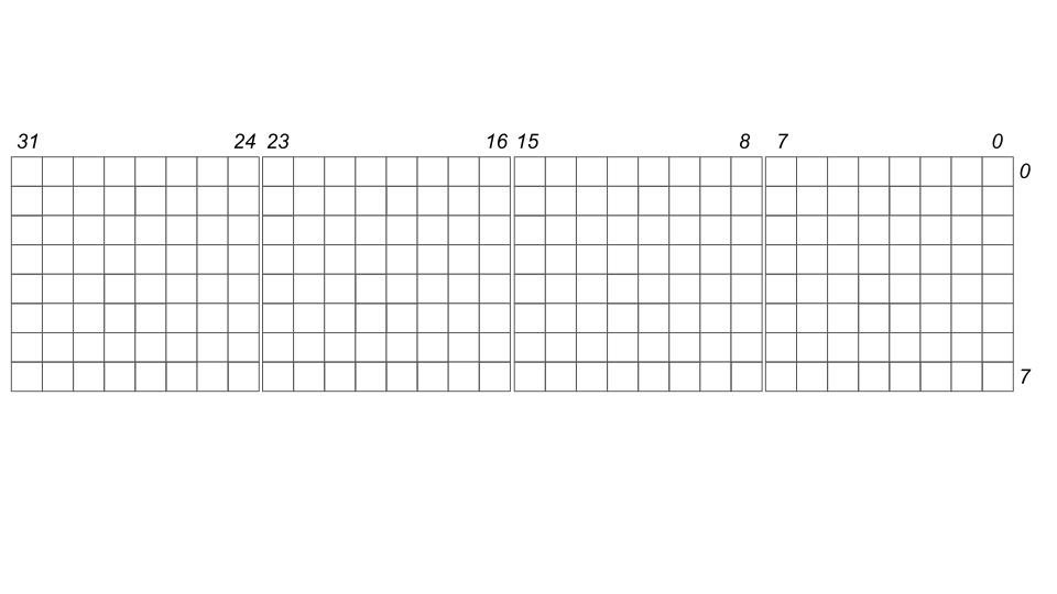
Take a moment to internalize this.
Our screen buffer is going to directly map to the LED array. Let's look at how our screen buffer is declared in 6190.h:
uint32_t screen_buffer [8];
screen_buffer is an array containing 8 32-bit unsigned integers.
screen_buffer[0]corresponds to the top row of the LED display andscreen_buffer[7]corresponds to the bottom row.- The 31st (most-significant) bit in each of the
screen_bufferarray entries corresponds to the leftmost column of the LED display. - The 0th (least-significant) bit in each of the
screen_bufferarray entries corresponds to the rightmost column of the LED display.
To ensure that you understand how screen_buffer works, answer the following questions. You may find it helpful to reference ascii.h.
screen_buffer and leaves other pixels unchanged.
"6", what value should be stored in screen_buffer[3]? (Recall that the first character in a string should be displayed on the left side of the screen.) Answer in 32-bit hexadecimal.
"6004", what value should be stored in screen_buffer[3]? Answer in 32-bit hexadecimal.
7.2) drawAsciiString
Complete the function drawAsciiString(char* string_to_draw), which is defined in main.c:
drawAsciiString()takes in one argument, a pointer to the char array to be displayed.- Fill the 8x32 screen buffer (a length-8 array of unsigned 32-bit integers), named
screen_buffer(it's declared in6190.h, so you can just use it without needing to declare it), with the correct data fromascii.h. There should be one character in each of the four 8x8 blocks on the LED array. - Once the 8x32 screen buffer has been filled, use
drawBuffer()to transmit the buffer data. - If the string to draw has more than 4 characters,
drawAsciiStringshould print the first 4. - If the null-terminating character is reached before
screen_bufferhas been filled, fill in the rest of the screen buffer with 0's. - Depending on your implementation, you may need to use
eraseBuffer()in order to resetscreen_bufferbefore filling it with data.
string_to_draw) and seeing how that prints out on the output. It won't pass any test cases, but it will give you a better idea of how individual characters are rendering.
In your main while loop, you should insert a call to drawAsciiString where the printf statement from the previous part is. You may find it helpful to keep that print statement there for debugging purposes.
Compile your project and flash it to the board.
Just like you did in the previous part, you can fill in a char array using switches, pressing BTNF to "enter" each character. Make sure to include the null-terminating character after you've entered a few (displayable) characters.
If you called drawAsciiString in the correct place (and you made sure to use displayable characters in your char array), something should print on the LED array when you enter the null-terminating character. If your implementation of drawAsciiString is correct, that something should be your message.
The LED array should update after entering the null-terminating character, not with each individual input.
Here's a message you can use for testing purposes.
- 0x4B = 0100_1011
- 0x26 = 0010_0110
- 0x52 = 0101_0010
- 0x43 = 0100_0011
- 0x00 = 0000_0000
It should print "K&RC".
Note: Since there are just 4 8x8 blocks on our LED array, our system will only be able to display the first four characters of a given string (not including the null-terminator, since that would just be rendered as a blank 8x8 square). The postlab will address this!
Demonstrate your system displaying the first four characters of a string (entered via switches) on the LED array.
You can remove the wires connecting the switches and buttons to the ESP32. However, do not disconnect the LED array, as the postlab will use that.
8) Code Submission
Submit your main.c and 6190.h files in a zip file named None_lab2.zip.
To create the zip file, you can select the folders/files you want, right click, and look for the option to compress these files.
Alternatively, you can run one of the following commands in the terminal:
If you're on MacOS or Linux or Command Prompt:
zip None_lab2.zip src/6190.h src/main.c
or for Windows Powershell users,
Compress-Archive -Path src/main.c,src/6190.h -DestinationPath None_lab2.zip
main.c and 6190.h files here in a zip file: Name the file None_lab2.zip for this assignment.
Footnotes
1Specifically, UTF-8
2This is because we designed the green PCB so that pressing a button creates a connection to ground, which corresponds to a digital 0. Releasing the button removes that connection, and we set up the GPIO pin on the ESP32 to interpret "no connection" as a digital 1 (using an internal pull-up resistor).
3Note, we are trying to index into an array with a character, but indexing requires integers. Try casting the character as an int