Hit the Bit
Please Log In for full access to the web site.
Note that this link will take you to an external site (https://shimmer.mit.edu) to authenticate, and then you will be redirected back to this page.
This postlab has 1 checkoff at the end. Make sure you complete it and upload your code to receive credit!
1) Hardware Setup
Here's the circuit diagram for this week's postlab (as shown at the end of the lab):

1.1) LED Display
You should have created a new project and wired up the LED display at the end of lab1. If you haven't done that yet, please do that now.
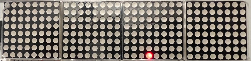
If you've already done that, take out your kit and open up your 6190_postlab1 project directory. Upload (flash) the project as-is to the board and ensure that the board looks like this
Now we'll need to set up the switches.
1.1.1) Bit Switches
For this game, we'll need 8 switches. The switches are just like the buttons from the lab except they are not "momentary", rather they slide and stay put where they are. We need to connect our eight switches like so:
SW7to9SW6to7SW5to6SW4to5SW3to4SW2to3SW1to20SW0to21
Make sure to also connect the ground pins (GND) as well! You can use the schematic above to wire it up.
Let's get into the game.
2) Hit the Bit
For our first postlab we're going to build a slightly-more-complicated variant of the classic early computer game1 from the Altair 8800 called "Kill the Bit". We will call our version "Hit the Bit." The game consists of two parts:
- A game "screen" consisting of an eight-long array of LEDs
- A set of eight toggle switches as a user input
Historically, the game would start with one single LED illuminated which would shift rightwards through it, wrapping around when it reached the end, sort of like this:
The "game" part of the situation came in from the switches. Each of the eight switches corresponded to one of the 8 LEDs. The user's goal was to flip the eight switches into a pattern that matched the state of the eight LEDs. Each switch mapped to an LED:
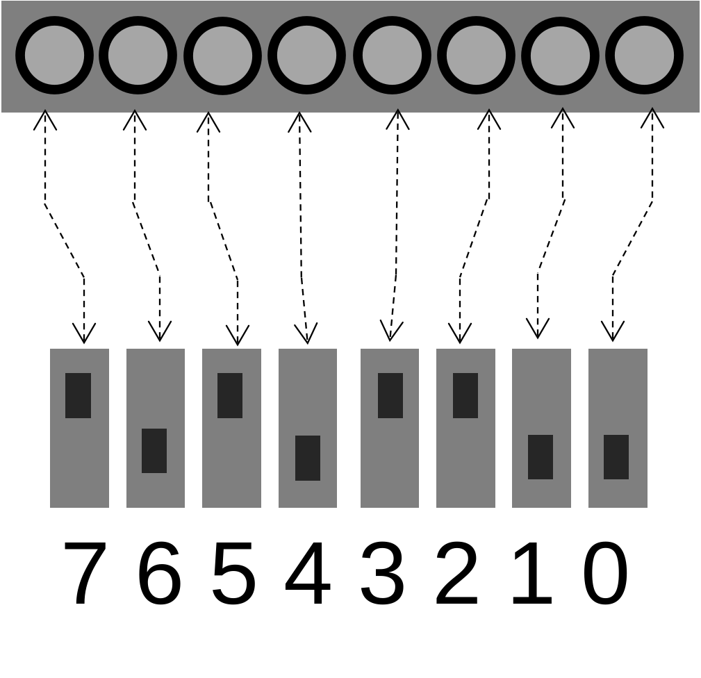
Upon flipping a switch, the values of all eight switches are sampled and compared to the LED game board. Switches that match their corresponding LED partner would result in the next LED state being 0 (turning off the LED). Switches that differed (whether LED on and switch OFF or vice versa) would result in the LED to the right turning ON. One switch array transition could happen per time step, so, depending on your switches and starting LED grid state, it might be impossible to hit the bit in one step. You might have to do several switch permutations before you can zero out the board. The goal is to eliminate all bits. However, the speed of the shift and switch positions make this potentially challenging.
2.1) Examples
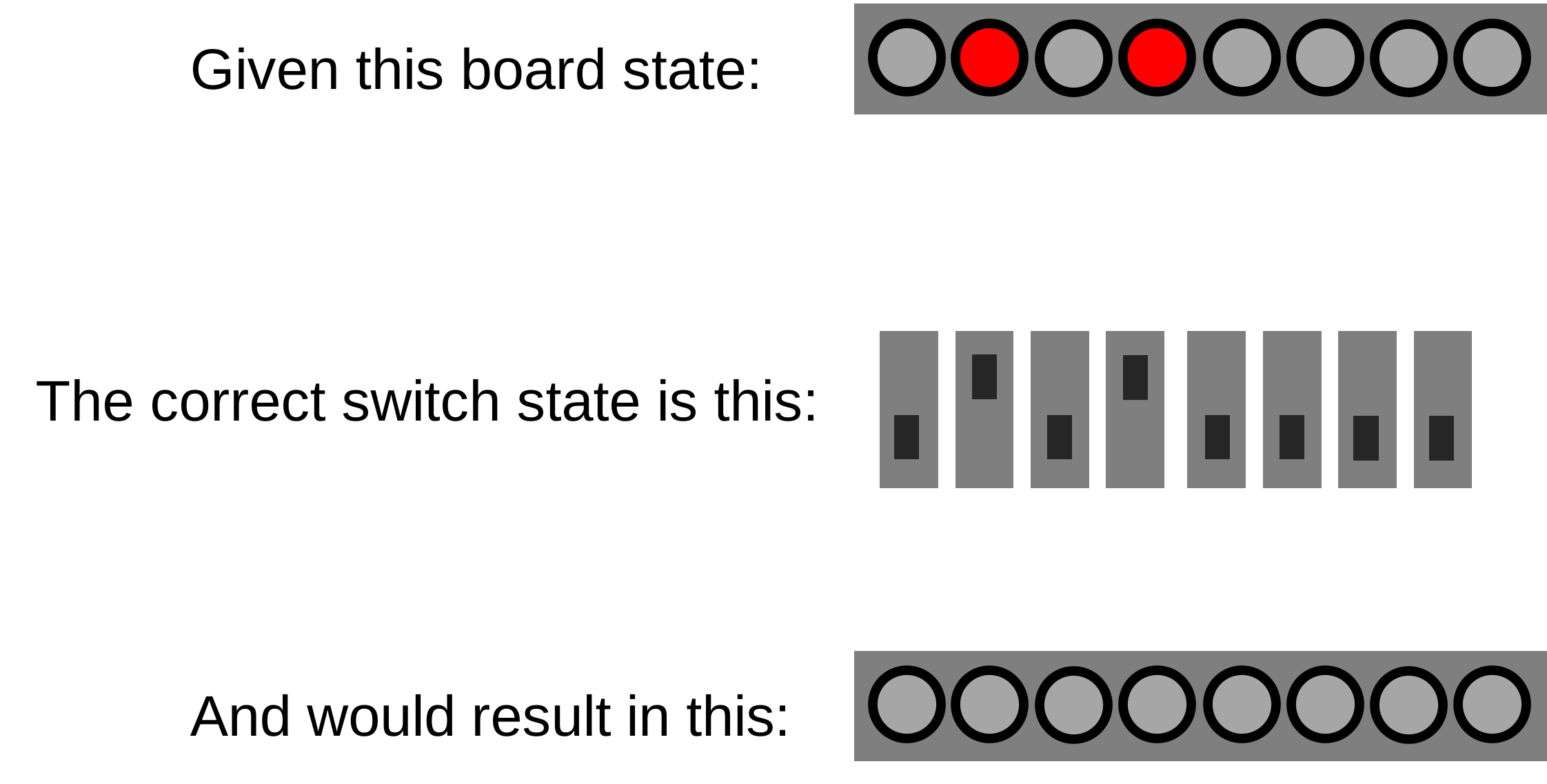
Here's a case where the user moves the switches into the correct state for a given LED game board resulting in all the LEDs turning off:
Here's an example where the user moves the switches into the incorrect state for a given LED game board, resulting in a net gain/loss of 0 LEDs.
- The user got the left "ON" LED correct, so that one turned off.
- However, the user was incorrect in switches SW4 and SW3 so both of the corresponding LEDs are turned on.
- Everything shifted to the right by one when updating, which happens regardless of correctness.
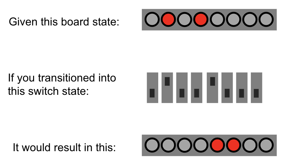
The challenging thing is, you can only move one switch per turn. As a result, depending on what your switches are and what your LEDs are, there may be no perfect move on any given time step. You may need to do multiple steps to get to the end.
Here's the game in action:
Are you excited? We're excited. Let's get into it.
3) The Code
Let's take a look through the main.c file.
- Task 1: Get the LED-shifting behavior working
- Task 2: Get the switch inputs working
- Task 3: Determine the right comparison to do between the LEDs and the switches
3.1) Slide to the Right...then Wrap
Our first step will be to get the shifting-and-wrapping working. Write a function updateLeds that takes care of the right-shifting-and-wrapping behavior. It should take in a pointer to the integer leds whose bottom 8 bits represent the values of the 8 LEDs in our game. The upper 24 bits should be set to 0 and will be unused.

3.1.1) A Super Important Note about Programming your Board
Now, in order to program your board, SW7 must be in the upright position! We need to do this any time a switch is connected to GPIO9. We're not gonna dwell on why this happens in this class, but if you're curious, Google "ESP32-C3 strapping pins".
3.1.2) Ok now let's actually program the board
Making sure SW7 is in the UP position, copy your implementation from above into the updateLeds function in main.c, then compile and flash the project to the board.
It should be giving you the following behavior ad infinitum.
Very juicy.
3.2) Get the Inputs
Next, we need to get the switch values. For this, we have the getInputs function. This function should return an integer whose lower 8 bits encode the values of all eight switches in order. For example, switch SW0 should have a value encoded in the 1's place. SW1 should be encoded in the 2's place, SW2 should be encoded in the 4's place etc... Note the upper 24 bits of the int that this function returns are unused, but that's ok. We don't really care about them.
Since we are trying to read inputs, we should use pinRead() here. You can also use switch_pins (see its definition in your main.c file) if needed.
3.3) The Comparison
The final task you need to complete is modify the logic in this line of the starter code found in the main while loop:
leds = leds; //TASK 3 (update so new_switches alters leds!)
Does it need to stay a single line? No, you could do multiple lines. But think about what we want to do. We want to compare the value of all eight LEDs (encoded in the lower eight bits of leds) to the value of all eight switches (encoded in the lower eight bits of new_switches). On a bit-by-bit basis we want to have the following behavior:
- If the LED is 0 and the Switch is 0, the result should be a 0 (match/correct)
- If the LED is 0 and the Switch is 1, the result should be a 1 (mismatch/incorrect)
- If the LED is 1 and the Switch is 0, the result should be a 1 (mismatch/incorrect)
- If the LED is 1 and the Switch is 1, the result should be a 0 (match/correct)
The eight bits of calculation should then be re-stored in leds.
Is there a single operation that could do this for us? Is there a "bitwise" version of that operation?
When you have what you think is correct, try it out on your device. Plug in your board, and, making sure that SW7 is UP, compile your code and flash it.
The result should be a game that works like this:
If your board lights up as expected but the LEDs don't update correctly, make sure that SW7 is up!!
The value of TIME is currently set to 1000 in order to slow down the loop enough for you to debug if needed. Once you've got the hang of the game, lower the value of TIME to be around 400.
To make the game challenging:
- set your switches to a random position at the start
- set your initial LED state to a random value at the start
- Increase the speed further by lowering the value of
TIME.
Enjoy it. A game that you wrote!
Show your game to a staff member! Be prepared to answer questions about your implementation.
4) Upload Your Working System
For final grading on this postlab, upload a zip file called None_postlab1.zip containing your main.c file.
You can run one of the following commands in the terminal:
If you're on MacOS or Linux or using Windows Command Prompt:
zip None_postlab1.zip src/main.c
or for Windows users using Powershell,
Compress-Archive -Path src/main.c,src/6190.h -DestinationPath None_postlab1.zip
None_postlab1.zip for this assignment. Thanks!