Lab 1: Introduction
Please Log In for full access to the web site.
Note that this link will take you to an external site (https://shimmer.mit.edu) to authenticate, and then you will be redirected back to this page.
This lab has 3 checkoffs and 1 code submission. These are all required in order to complete the lab.
Checkoffs are placed throughout the lab. A checkoff is a short discussion with a staff member where you'll demonstrate your working system and then answer some questions about your implementation and underlying concepts.
1) Attendance

2) Software Setup
If you haven't already, please complete the setup lab.
3) Labkit Setup
All of the labs for the class will involve your 6.190 labkit, which will be made up of various parts. If you unpack your kit, you should have all of the items in this picture:
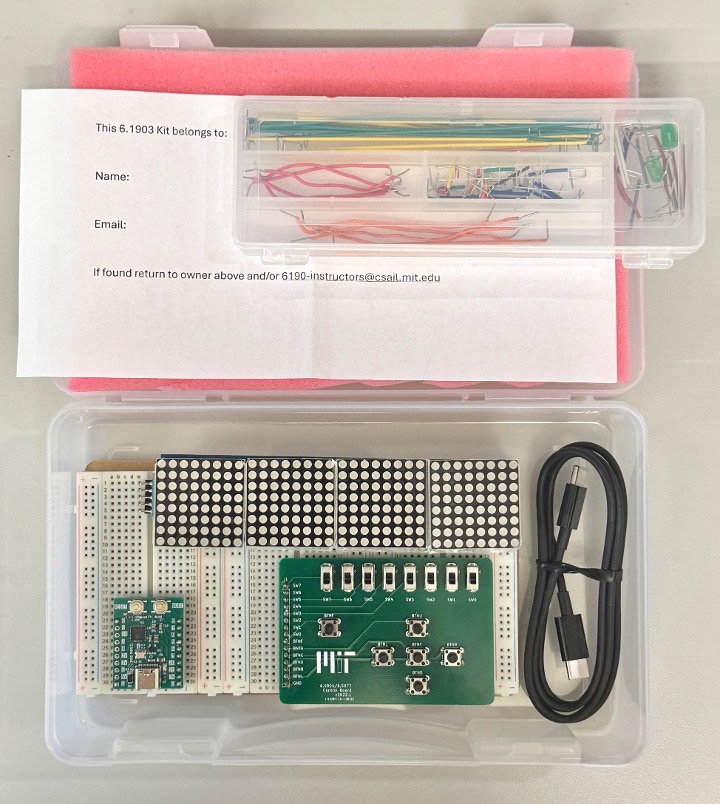
Your kit includes: three breadboards, an ESP32, a green printed circuit board (PCB) with buttons and switches, an 8x32 LED display, a USB-C to USB-C cable (or a USB-A to USB-C cable), a wire kit, and a slip.
No need to dwell on the names of things (yet, we'll get there), just make sure that you have all of the items shown in the above image. If you don't, please let a staff member know.
Let's first dive into the main part of our labkit:
3.1) Breadboards
Your kit has three breadboards, which we'll use to create electrical connections between various circuit components. Each of the breadboards should look more like the one on the left side of the image below. When building circuits, you'll put wires and pins into the holes to create connections between different areas of the board (and the circuit components that are connected to those areas of the board).
The breadboard on the right shows how things are actually connected under the hood. (Your breadboards as given WILL NOT look like this, someone at some point disassembled one so you don't need to. Please trust the image and don't rip your board apart.) Any holes in the image on the left that correspond to the same piece of metal in the image on the right are connected.
- On the left and right sides of the board, we have two vertical "rails1" (these are often used for power (+) and ground (-) to make them easily accessible from all of the locations on the breadboard).
- On the middle section of the breadboard, connections are horizontal. Do note how there's a gap on the center of the breadboard; so the left half and the right half of the breadboard are not connected.
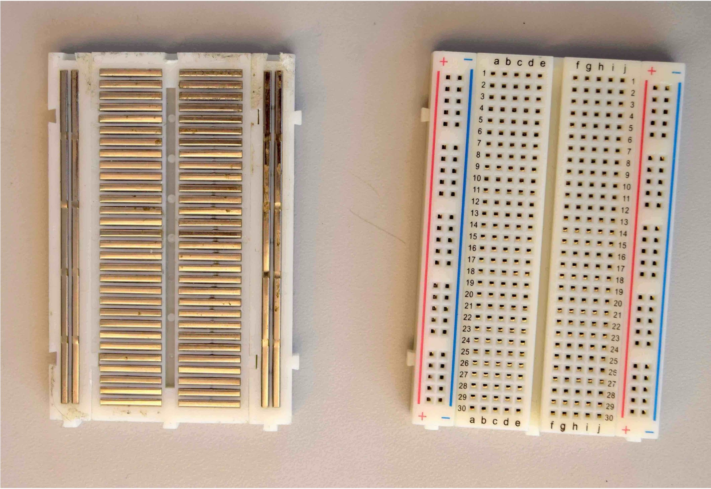
Please don't do this to your breadboard.
If you would like to connect two locations that aren't connected by the breadboard (on the same piece of metal), you must use a wire. Note that this is also needed to connect the various power rails to each other.
3.2) ESP32
The development board we'll be using in this class is an Espressif ESP32-C3 board. Moving forward, we'll just call this the ESP32.
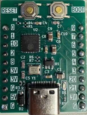
ESP32-C3 board (ESP32 for short)
This board has a lot of cool stuff on it, including the RISC-V microprocessor that we'll be programming.
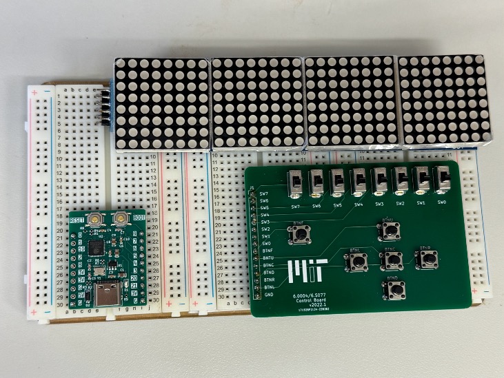
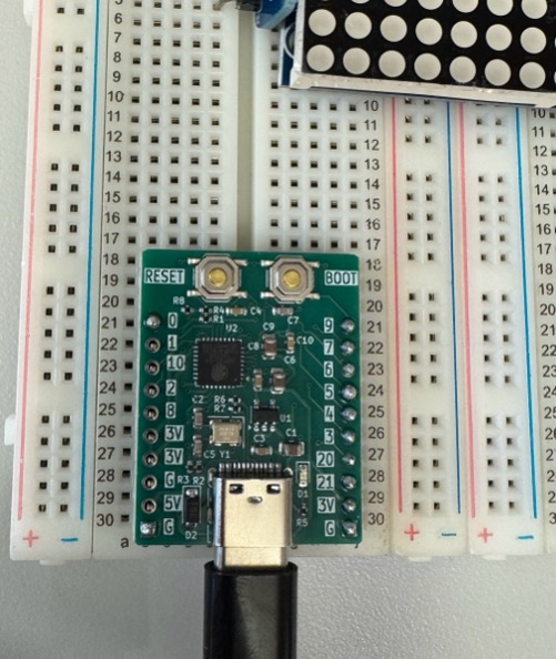
Your ESP32 should already be in the correct place on the breadboard, with the top-left pin in row 21 of column B on the leftmost breadboard. If it is not there, please move it, so that it is. All of the reference images we'll use in this lab assume that the ESP32 is in this location.
3.3) 6.190 Printed Circuit Board
Next, we have a green printed circuit board (PCB) with a bunch of switches and buttons that we'll be using as inputs to our system.
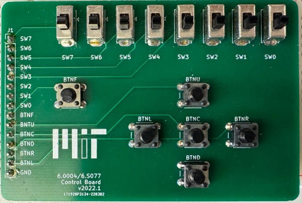
Your 6.190 Control Board
This should be in column e (it's okay if it's in column d) of the middle breadboard, with the topmost pin (labeled SW7) in row 16. Verify that it's in the right place, and move it there if it isn't.
3.4) LED Array
The final permanent fixture on our breadboard is an 8x32 LED display. You can think of it like any other display, with each LED being a pixel. So we won't be getting HD or anything on this, but we'll be able to do some cool things.
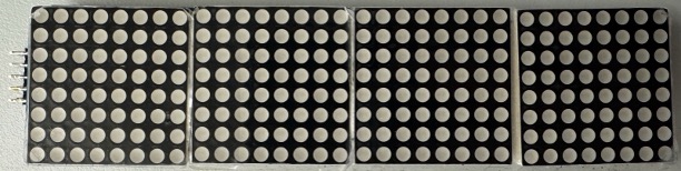
Similar to the PCB, there are some pins perpendicular to the board, facing downward. Make sure that the pins are in column e of the leftmost breadboard, with the top pin in row 1. You can use the image of the entire system above for reference.
You should not remove these three components (the ESP32, LED Display, and printed circuit board) in between labs; they should stay where they are.
3.5) Connecting your ESP32 to your Computer
Your labkit comes with a USB-C to USB-C (or a USB-A to USB-C) cable.
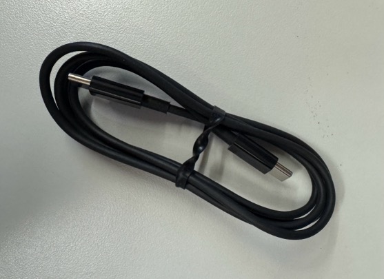
The USB-C side will plug into your ESP32 like so:
4) Lab 1 (Finally)
4.1) Our First Circuit
You'll need two LEDs for this part -- please come to the front of the room and get them from a staff member if they are not already in your kit.
Now we're going to connect some external devices as inputs and outputs to our ESP32 microcontroller, like shown here in this schematic (fancy word for circuit diagram).

Read on for the details of how to wire everything up. You have a wire kit in your lab that you should use for this. It's also a good idea to keep your ESP32 unplugged from the computer as you wire things up.
4.1.1) Inputs: Printed Circuit Board
Our printed circuit board will provide inputs to the system, as it will in most of our labs.
Today, we'll be using two of the buttons, BTNL and BTNR. Connect BTNL to pin 3 on the ESP32 board, and connect BTNR to pin 4. Also connect the GND (short for ground) on the printed circuit board to the G on the bottom right of the ESP32 board.
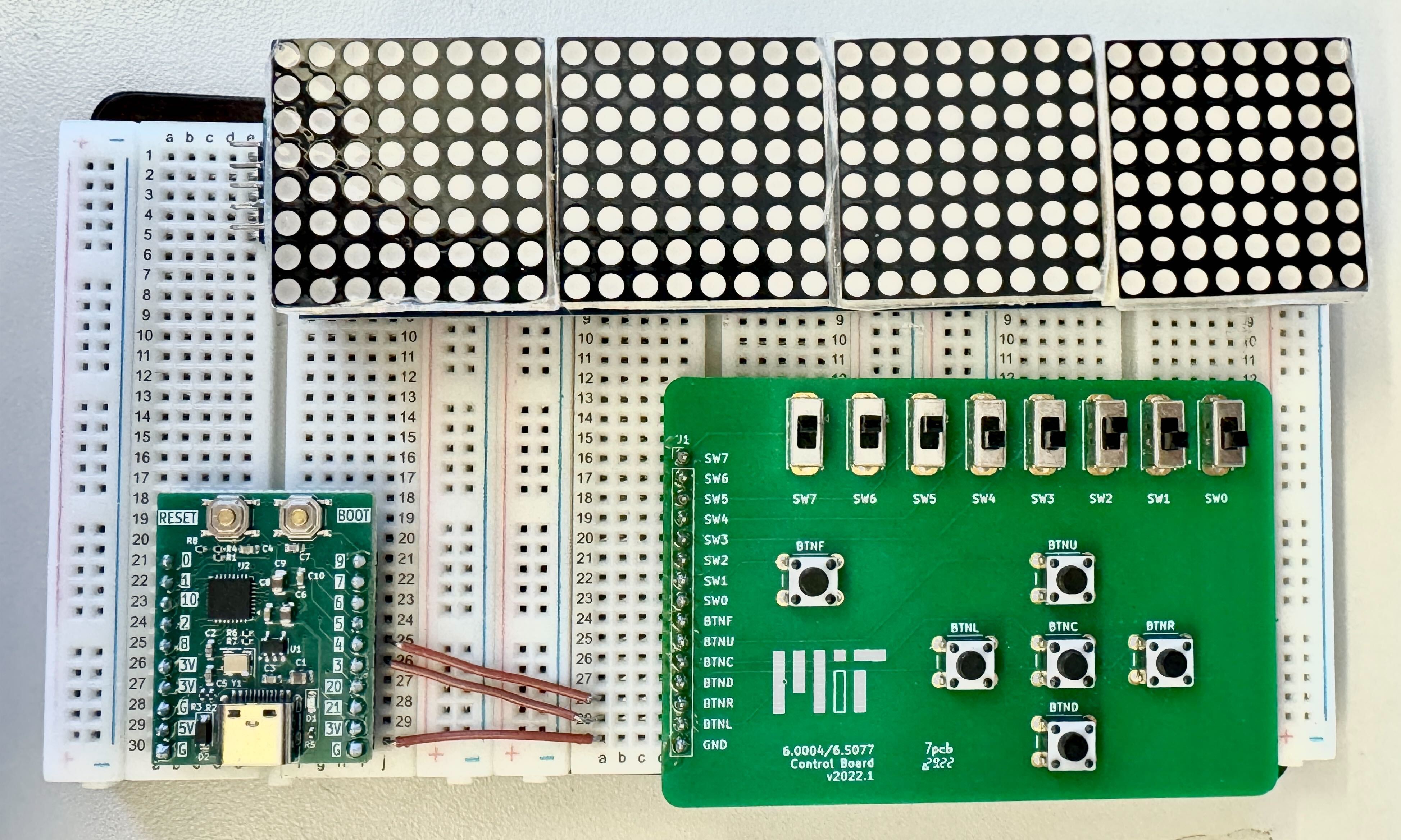
Nice. Try to keep wires as flat to the breadboard as possible.
4.1.2) Outputs: LEDs
Today, we'll be using two LEDs as outputs. If you look at one of your LEDs, you'll notice that one leg is longer than the other. Current can only flow through LEDs in one direction (take 6.2000 and 6.2500 to learn why), so it really matters how we orient each one.
The longer leg should be connected to a GPIO (General Purpose Input Output) pin on the ESP32, and the shorter leg should be connected to ground. So, the longer leg will be on the right and the shorter leg should be on the left. (the long leg of the LED corresponds with the "bottom" of the triangle in its schematic symbol, and the short leg corresponds with the separate line part on the top part of the triangle symbol)2.
Before we tackle the LEDs, though, we are going to take advantage of the ground rail on our breadboards. Connect the GND (short for ground) pin in the bottom left corner of your ESP32 to the blue rail all the way to the left on your breadboard. Now, any of the holes in that leftmost vertical column will be ground. This will make it easier to connect the shorter leg of our LEDs to ground.
Note that this vertical rail will only be connected to ground if it is connected to the GND pin on the ESP32.
Connect everything like shown below, using GPIO pins 2 and 8 as our output pins. Don't forget the connection from GND on the ESP32 to the vertical blue rail!
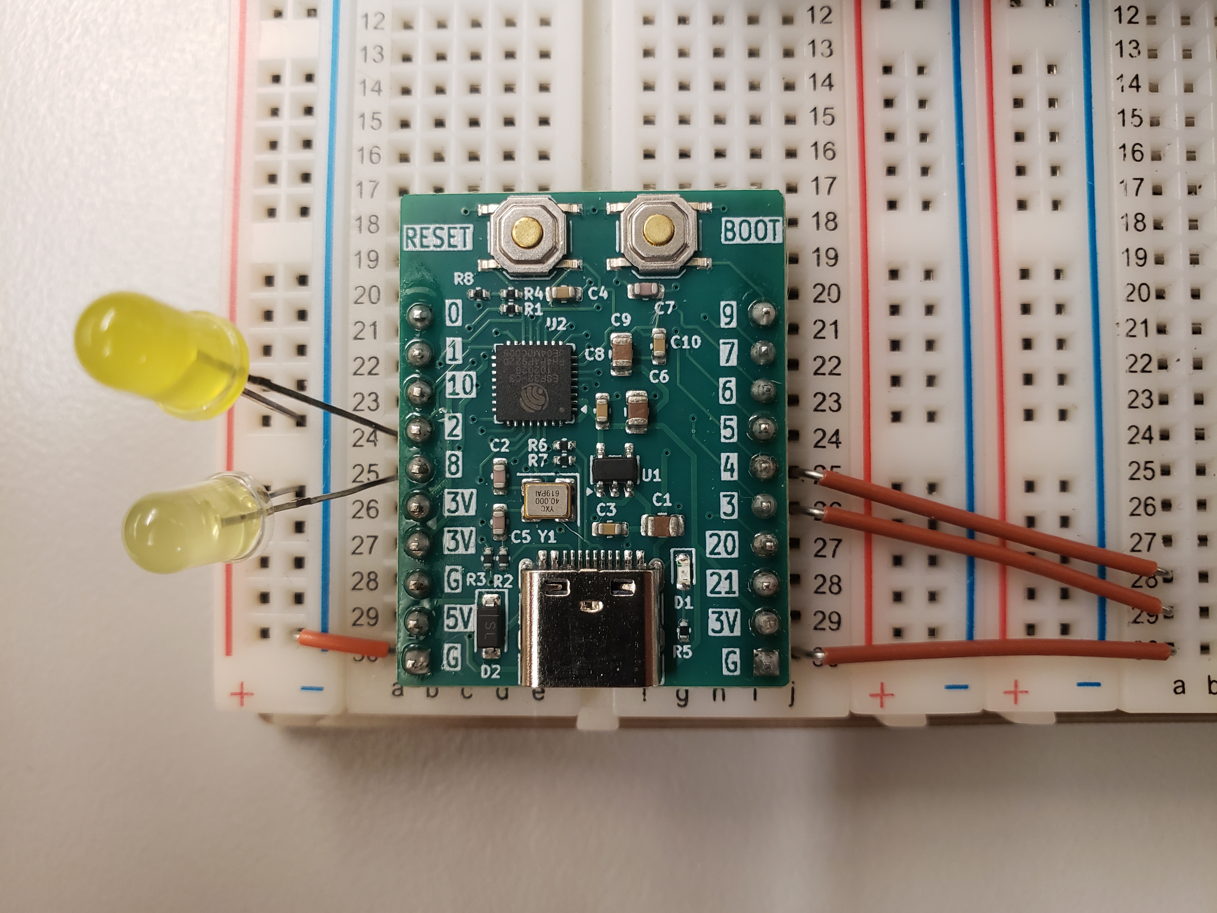
Here's our complete Lab 1 circuit:
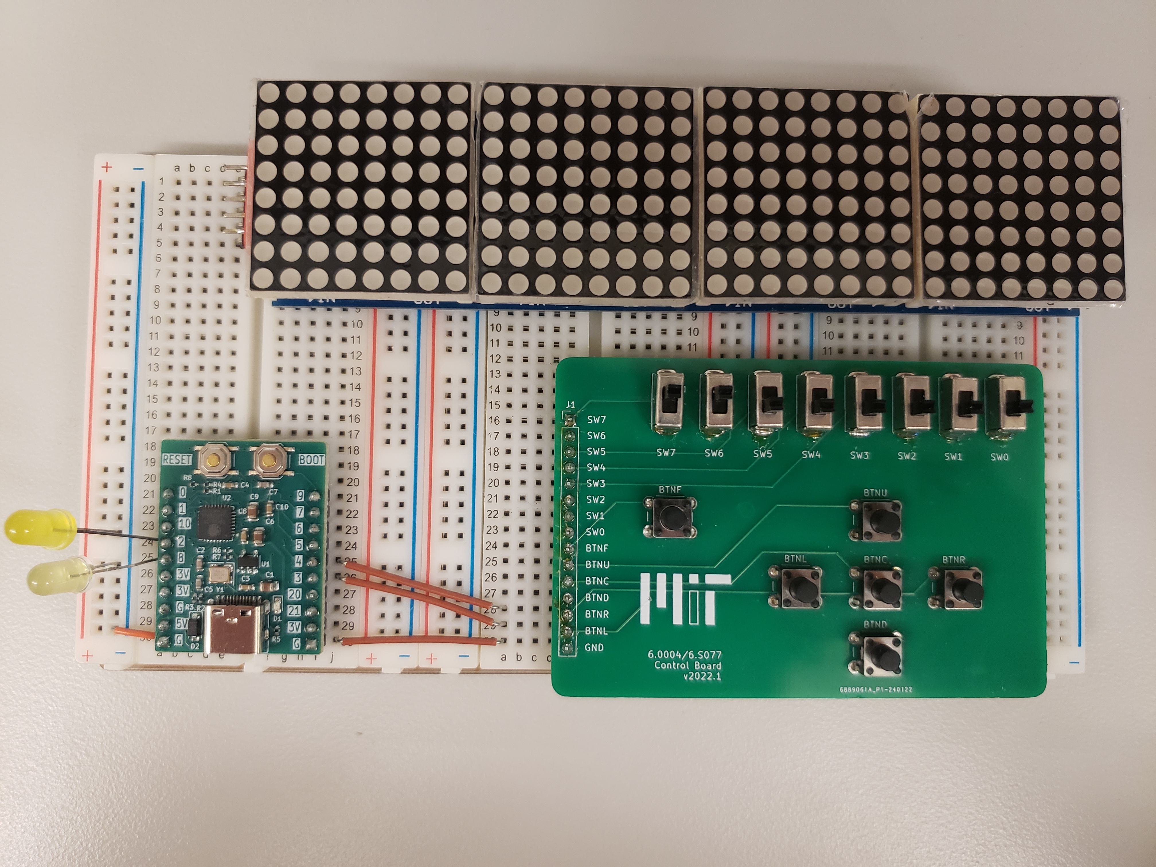
Nice work
4.2) Software and Hardware
Buttons take human mechanical signals and convert them to electrical form. The LEDs take electrical signals and convert them to light signals for the purpose of human consumption. We can use the buttons as inputs to a circuit, perform computation on that information using our ESP32, and then convey the result to users with the LEDs.
If we were doing this with pure circuits, we'd use wires and transistors to make a dedicated algorithm and be done with it. However, a computational device, like the one we're working with, is more flexible. We can use software to control what and how we manipulate our input information and how and what we produce for our output information. This ability to write software that directly interacts with hardware is extremely powerful, and it's used in a lot of systems that surround us today, from cell phones to vehicles to medical devices. The laboratory exercises in this course will give you a taste of this.
5) Software Setup
5.1) 6190 Labs Folder
In order to make it easy for you to find all your 6190 labs in one place, let's create a folder called 6190 where we will put the starter code for each lab.
Move the test_project folder (from the lab0 setup) into the 6190 folder as well.
So your directory structure should now look something like this:
 6190
    |
    +--->test_project
        |
        +---> src
        |
        +---> build
What we'd like to do is keep all the labs and activities in this folder as you move through the course. So as you add additional labs into the course, this folder will start to look like the following:
 6190
    |
    +--->test_project
    |   |
    |   +---> src
    |   |
    |   +---> build
    |
    +--->6190_lab1
    |   |
    |   +---> src
    |   |
    |   +---> build
    |
   ...
5.2) Starter Code
Download the starter code for today's lab here: [Starter Code]. There will be two (2) files in the src folder:
main.c, your main C file. This file is our "entry point", a file that contains a function which the system will "start" from.6190.hA header file that contains definitions of microcontroller-specific constants and functions.
At the core of all of our projects will be two types of files:
- Main C file
- C header file
Extract the contents of the zip (by right clicking and choosing extract on windows or linux, or by double clicking on the .zip file on a Mac): Move this extracted 6190_lab1 folder into the 6190 folder created above.
In your terminal, navigate to the toplevel 6190 directory. From here, you'll be able to use the same build tools as were used during the setup lab. Before proceeding with lab1, make sure that you've reactivated the virtual environment that you created during the setup lab by running the following command (note you need to remember where you created that virtual environment too!):
For Mac/Linux:
source 61903_python/bin/activate
For Windows:
.\61903_python\Scripts\Activate
Now cd 6190_lab1 to begin working on lab 1.
If you would like some guidance in navigating the terminal, feel free to refer to the setup lab for more information or go on the queue for help!
Let's take a quick tour through the files we'll be using in this lab.
5.2.1) Main C file (main.c)
At the top of your main.c file are a couple of lines that start with #include. #include essentially indicates that the contents of the indicated file should be treated as if they were written in the current file. You can think of it as copying and pasting the contents of the file starting where the #include is.
We use < > to indicate a file (stdio.h below) that's defined in the C standard library, and we use " " to indicate a file (6190.h below) that we have created. We only use #include to import the contents of C header (.h) files here; but it can be used to import the contents of C source (.c) files as well.
stdio.h will allow us to use printf statements, which can be extremely helpful for debugging, and 6190.h contains course-specific function and constant definitions (some of which you'll write yourself today). We'll discuss header files more in the next section.
In this class, we will write all of the necessary #include statements for you in the starter code, so you will not need to write them yourself.
Today, the top of your main.c file has:
#include <stdio.h>  // anything defined in stdio.h is now defined in main.c
#include "6190.h"   // anything defined in 6190.h is now defined in main.c
After the file inclusions should come any helper functions and/or globally-defined variables. In our lab1 main.c file, we have one helper function, setup(). This helper function should be declared before it is used. If we were to put setup() below app_main(), the code would not compile.
At the bottom of the file, you will find our actual "entry-point" into the program, app_main(). Any C program we write will start in this function. You can see that it calls setup(), which has been declared previously in the file.
// This is where your program starts.
void app_main(){
    setup();
    while(1){

    }
}
Note that in most toolchains, this "entry-point" function is called main(). However, for the framework used for 6.190 labs it must be called app_main(). This function will always be declared for you in the starter code.
5.2.2) C Header file (6190.h)
We're going to have quite a few functions and constants that we will need to use for different labs, so we'll find it useful to keep them all located in a header file that we can reuse during each lab. As mentioned in the previous section, the contents of a header file can then be defined in main.c using an #include. We have named our course-specific header file 6190.h, since it will contain definitions specific to the hardware used in this class.
You will be updating and using this file throughout the semester, so it is important that you don't delete it/lose track of it after completing a lab. We will not provide replacements if you accidentally delete it or can't find it.
Looking at 6190.h, you'll notice some lines that start with #define, for example:
#define GPIO_BASE_ADDR 0x60004000
#define is used to declare a constant value for our program. This is actually quite different from using a variable declaration (for example int GPIO_BASE_ADDR = 0x60004000) in a few ways, the most notable being that the definition actually doesn't take up space in memory (like you'd expect from an int, for example). You can think of it as the constant value being pasted in whenever the constant name (above, its GPIO_BASE_ADDR) appears in your code.
6) General Purpose Input/Output (GPIO)
So now we have our LEDs and button(s) physically connected to our board, but how are we going to write software to interact with them?
The pins that we connected our LEDs and button to are called GPIO pins, which stands for General Purpose Input/Output. Before we can use these pins, we must configure them by writing values to specific memory addresses (also known as control registers) on the ESP32. Microprocessors have a (usually quite lengthy -- the manual for the ESP32-C3 is over 700 pages long) manual that includes these addresses.
We'll work with these addresses extensively, so software definitions for these memory addresses are defined in 6190.h. This will make our code much more readable -- someone reading your code won't need to search through the reference manual to figure out what the address 0x60004004 corresponds with, because they'll immediately see that the program accesses GPIO_OUT_ADDR.
Towards the top of your 6190.h file, we've outlined the different "base addresses" of the peripherals we'll be using in this course. Today, we'll be using the GPIO_BASE_ADDR and IO_MUX_BASE_ADDR.
/* Peripheral Base Addresses */
// Base address of section of memory dedicated to GPIO matrix
#define GPIO_BASE_ADDR     0x60004000
// Base address of section of memory dedicated to IO multiplexer
#define IO_MUX_BASE_ADDR   0x60009000
Farther down in the header file, we actually calculate each memory location, using an offset from its base address:
/* GPIO Memory Map Locations */
// EXAMPLE: The address for GPIO_OUT is offset from the GPIO base address by 0x0004, so we use the sum.
#define GPIO_OUT_ADDR      (GPIO_BASE_ADDR + 0x0004)
#define GPIO_ENABLE_ADDR   (GPIO_BASE_ADDR + 0x0020)
#define GPIO_IN_ADDR       (GPIO_BASE_ADDR + 0x003C)
#define IO_MUX_GPIOn_ADDR  (IO_MUX_BASE_ADDR + 0x0004)
So, we have these memory locations, but now you might be wondering what they mean and how we will read and write to them. Let's start with how we'll read/write to them. In most cases, we will need to either read a single bit in the 32-bit value or set a single bit in the 32-bit value to be either a 1 or a 0.
For example, each bit in GPIO_OUT_ADDR corresponds directly to a GPIO pin on the ESP32. If bit 9 in the 32-bit value stored in GPIO_OUT_ADDR is set to 1, then a digital high voltage will be sent to GPIO pin 9. If an LED was connected to GPIO pin 9, it would turn on. If, later on, bit 9 in the 32-bit value stored at GPIO_OUT_ADDR was set to 0, then a digital low voltage would be sent to GPIO pin 9, and that LED would turn off.
So, if we have a 32-bit value, we must be able to access and/or change just some of its bits, usually without modifying the other bits in the value.
6.1) Bit Manipulation
It's tempting to think of the values stored at these 32-bit memory locations as similar to Python lists, where each element is either a 0 or a 1, however, they are not represented that way in memory. The actual value stored at each memory location is merely a 32-bit value, and we are only able to access it in its entirety. So, we can't do something like value[5] to access the 5th bit in the value (wouldn't that be nice). However, we still need to access and modify individual bits in a given value. Enter bit manipulation.
There are three main operations we will want to carry out.
- Setting one bit in the n-bit value so that the bit is equal to 1 (without modifying any of the other bits in the value).
- Clearing one bit in the n-bit value so that the bit is equal to 0 (without modifying any of the other bits in the value).
- Reading one bit from the n-bit value (without modifying the value itself).
Note that we 0-index when talking about bits, so the rightmost "least-significant" bit is the 0th bit.
6.1.1) Setting a Bit
Let's say we have this n-bit value, and we want bit 6 (zero-indexing from the rightmost bit) to be 1:
When you want to set bit 6, meaning that you want to set the 6th bit in the value to be equal to 1:
- If bit 6 is already equal to 1, it should stay equal to 1.
- If bit 6 is equal to 0, it should become equal to 1.
- Every other bit in the value should remain equal to its current value (you should not modify any of the other bits).
Believe it or not, all of this can be done using just one line of code, using bitwise operations!
val while preserving the original value of all the other bits?
6.1.2) Clearing a Bit
Now, we want bit 2 in an arbitrary n-bit value to be equal to 0. This is known as clearing bit 2.
When you want to clear bit 2, meaning that you want to set the 2nd bit in the value to be equal to 0:
- If bit 2 is already equal to 0, it should stay equal to 0.
- If bit 2 is equal to 1, it should become equal to 0.
- Every other bit in the value should remain equal to its current value (you should not modify any of the other bits).
Just as with setting a bit, all of this can be done using just one line of code.
val while preserving the value of all the other bits?
In C, the answer choices above can also be equivalently written as the following syntax:
val &= (1 << 2);
val |= ~(0 << 2);
val &= ~(1 << 2);
val ^= (1 << 2);
6.1.3) Reading a Bit
So, now we know how to write to individual bits in a given value, but we will also want to be able to read them.
Keep in mind that a bit can only have the value 0 or 1, however C doesn't have a single-bit data type.
val in the 32-bit integer variable bit?
Ok, now let's actually start writing code, now that we have a better idea of the operations we'll be performing.
6.2) GPIO Configuration
Before we can actually use a GPIO pin, we must configure it as either an input or an output. So, your first task will be to configure the GPIO pins you'll be using today.
6.2.1) Some Pointers
Our GPIO-related functions (as well as others we'll write throughout the course) will require us to access and modify specific memory addresses. At this point in your programming journey, you're likely used to accessing values using a variable name. However, in the case of these memory-mapped controllers, we are only given the address where a given value is stored in memory (these addresses are defined in 6190.h). So, we must use pointers to access and modify these values. Let's walk through how we would do this.
Given a memory address, like GPIO_ENABLE_ADDR, we'll first declare a pointer that is equal to this memory address.
int *gpio_enable_addr = (int*) GPIO_ENABLE_ADDR;
We can then read the value stored at GPIO_ENABLE_ADDR using the dereference operator (*):
int gpio_enable_val = *gpio_enable_addr; // puts 32-bit value stored at GPIO_ENABLE_ADDR into variable gpio_enable_val
We could also update the value stored at GPIO_ENABLE_ADDR:
*gpio_enable_addr = 500; // writes the 32-bit number 500 to memory address GPIO_ENABLE_ADDR
6.2.2) GPIO Pin Setup
We've declared a function,pinSetup(), in 6190.h that takes in two arguments:
int pin_num: GPIO pin numberint mode: GPIO_INPUT (0) or GPIO_OUTPUT (1)
Complete pinSetup(). It should:
- Configure a GPIO pin
pin_numto be an input ifmodeis 0 (GPIO_INPUT) - Configure a GPIO pin
pin_numto be an output ifmodeis 1 (GPIO_OUTPUT). - Return nothing (note the
voidreturn type).
To configure pin n to be an input:
- Set bits 8 and 9 in the value stored at
io_mux_gpio_addr(which is the memory address that corresponds to the IO multiplexer for GPIO pin n) to be equal to 1.
Bit 8 at the address IO_MUX_GPIOn_ADDR + 4*n corresponds to enabling the internal pull-up resistor for GPIO pin n. It will "pull" the input "up" (as in the name) to be 1 in the case that our input isn't directly connected to ground. This will ensure that our input doesn't just float between 0 and 1 in that situation.
Bit 9 at that address corresponds to enabling input for GPIO pin n.
To configure pin n to be an output:
- Set bit n in the value stored at
GPIO_ENABLE_ADDRto be equal to 1. This enables output for GPIO pin n.
Please complete pinSetup() in the box below by updating the lines marked // YOUR CODE HERE. Once it passes all of the test cases (you'll see a green 100%), copy and paste your code into the pinSetup() function in 6190.h.
6.2.3) Program-specific Setup
Now that we have a general pinSetup() function, we need to use it in our program. Uncomment these lines in the starter code (in the setup() function)
// pinSetup(LED1, GPIO_OUTPUT); // Configure pin connected to LED1 as output
// pinSetup(LED2, GPIO_OUTPUT); // Configure pin connected to LED2 as output

// pinSetup(BTNL, GPIO_INPUT); // Configure pin connected to BTNL as input
// pinSetup(BTNR, GPIO_INPUT); // Configure pin connected to BTNR as input
This will configure the GPIO pins connected to BTNL and BTNR as inputs and the GPIO pins connected to LED1 and LED2 as outputs.
It's important to make sure that we always configure a GPIO pin before we use it; an unconfigured pin will result in unexpected behavior, which we definitely don't want.
main.c
6.3) Writing Outputs
Now that we've configured our pins, we want to use them. Let's first implement a function that will allow us to write to outputs. We've declared a function, pinWrite(), in 6190.h. It takes in two arguments:
int pin_num: GPIO pin number (0 - 31).int value: digital value (0 or 1) to write to GPIO pin
Complete pinWrite(). It should:
- Set bit
pin_numin the value stored inGPIO_OUT_ADDRto be equal tovalue. We have defined a pointer to this value for you, and we have also sanitizedvalueto always be either 1 or 0 for you. - Return nothing (note the
voidreturn type).
Please complete pinWrite() in the box below. Once it passes all of the test cases (you'll see a green 100%), copy and paste your code into the pinWrite() function in 6190.h.
Once you have copied your pinWrite() code over to 6190.h, uncomment these two lines of code in the app_main() function (towards the bottom of main.c).
// pinWrite(LED1, 1);  // Turn LED1 on
// pinWrite(LED2, 0);  // Turn LED2 off
Make sure you are still in your 6190_lab1 directory by running pwd to see your current working directory.
First, compile your code using the llp-bc compile ./ command. This will take approximately 20 seconds. If you made any syntax or other errors in your code, they will get caught at this stage and you should pay attention to the errors that are returned by the tool. Once you've fixed any errors, you should get back a success message and along with that is a bit file that you can then flash (program) the microcontroller with.
In order to program the microcontroller run the llp-bc flash ./** (same command as in the setup lab). This will take a second or two to flash your board and when that's done, your board is programmed! See if it is working correctly!
Your system may not be working correctly, in which case you likely have a functional error or mistake of some type. Maybe the code you wrote, while syntactically correct, is functionally incorrect for what we want to be doing. Or maybe there is a wiring issue. Or maybe both. You'll need to debug.
pin_num arguments (so that LED2 is in the first line and LED1 is in the second line), the LED connected to GPIO pin 8 should be off and the LED connected to GPIO pin 2 should be on.
6.4) Reading Inputs
We've declared a function, pinRead(), in 6190.h. pinRead() takes in one argument.
int pin_num: GPIO pin number (0 - 31).
Complete pinRead. The function should:
- Return the value (0 or 1) of bit
pin_numin the value stored atGPIO_IN_ADDR. We have defined a pointer to this value for you.
Please complete pinRead() in the box below. Once it passes all of the test cases (you'll see a green 100%), copy and paste your code into the pinRead() function in 6190.h.
Once you have copied your pinRead() code over to 6190.h, you can test your pinRead() function on your system by uncommenting these lines of code from the app_main() function in main.c,
// int x = pinRead(BTNL);  // Read value of BTNL
// if (x == 1){
//     printf("button not pressed\n");
// } else if (x == 0){
//     printf("BUTTON PRESSED!\n");
// }
With that change made (and saved), recompile your code (llp-bc compile ./) and then, assuming no errors, upload your new program to the board using llp-bc flash ./. Then, open the serial monitor with llp-bc monitor, and make sure the printed messages align with what you'd expect.
6190.h for the definition of BTNL.)
button not pressed prints when BTNL isn't pressed, and that BUTTON PRESSED! prints when BTNL is pressed.
Note that the digital input is equal to 0 when the button is being pressed and 1 when the button is not being pressed. This is because we create a connection to ground when the button is pressed, and when the button is not being pressed, a pullup resistor pulls the input voltage to be high.
The big thing you'll need to remember from this is that 0 corresponds to a button being pressed.
6.4.1) The Need for an Infinite Loop
When looking at the above lines of code, you might have noticed that our program contains an infinite loop. In many situations, infinite loops are seen as a bug, so, why do we need this?
Let's use our button push code as an example. We want our program to constantly be checking if our button is pressed, rather than just checking once and terminating. Computers move from instruction to instruction so quickly that you would pretty much need to be pressing the button before you started running the program if that's what you wanted the code to recognize. The chance that you would just press the button at the exact same time that your program reads the GPIO pin would be pretty much nonexistent.
So sure, without a loop, the program would still be getting input from the outside world, but just at that one point in time, which isn't particularly useful for us.
Usually, our programs will look something like this at a high level:
int app_main(){

    /* setup code here that only needs to run once.
    configuring hardware, initializing variables, etc. */

    while(1){
        /* code here that periodically checks for events (outside input,
        counter reaching threshold, etc.) with instructions on how
        to respond to them (or to a lack of them). */
    }
}
Our main loop will just run forever... waiting for events... ready to respond to them. At least until you unplug your board or you run out of power. Whichever comes first.
Show that the serial monitor prints "button not pressed" when the button (BTNL) isn't being pressed and "BUTTON PRESSED!" when the button is being pressed (the serial monitor might lag a little bit). Also be prepared to explain the current behavior of your LEDs.
7) Logical LEDs
Now we want to drive our LEDs (turn them on or off) based on user input to the system via the buttons (BTNL and BTNR). Modify the main loop of your program (inside the while(1) loop) so that:
LED1is on when eitherBTNLorBTNRare pressed, and off otherwise (including when both of them are being pressed). This is the behavior of an XOR (exlusive-or) logic gate.LED2is on only when bothBTNLandBTNRare pressed, and off otherwise. This is the behavior of an AND logic gate.
IMPORTANT: When BTNL is being pressed, will pinRead(BTNL) return a 0 or a 1?
Hint: If your LED2 is staying on consistently, it's not because the LED is broken! Think closely about the types returned by pinRead, and what the operations you're using on them are doing to all the bits in those values.
Remember every time you make a change to your code, you need to compile! and then flash. Changing code and then just flashing will only flash your previous build!!!!
Show that the behavior of LED1 matches that of an XOR gate and that the behavior of LED2 matches that of an AND gate.
8) Upload Your Working System
For final grading on this lab, upload a zip file called None_lab1.zip containing your main.c and 6190.h files. Please do not submit your entire project. It contains way too many files.
To create the zip file, you can select the folders/files you want, right click, and look for the option to compress these files.
Alternatively, you can run one of the following commands in the terminal:
If you're on MacOS or Linux or Windows Command Prompt:
zip None_lab1.zip src/6190.h src/main.c
or for Windows users (using Powershell),
Compress-Archive -Path src/main.c, src/6190.h -DestinationPath None_lab1.zip
main.c and 6190.h) here as a zip file: Name the file None_lab1.zip for this assignment. Thanks!
Before you leave today, you should do this prep for Postlab 1 -- note that there's a checkoff at the end.
9) Preparation for PostLab 1
Note there is a checkoff at the end of this section.
Before you leave today, we would like you to complete some of the setup for this week's postlab (there is a checkoff at the end to ensure that this has been done) to confirm that your LED display works as expected.
9.1) Wiring it Up
Unplug your ESP32 from your computer. Your ESP32 should be unplugged from your computer at the start of your checkoff, so make sure it's now uplugged. You should only plug your ESP32 back in with the supervision from course staff during checkoff 3. It's a good idea to remove your circuit from power before messing around with it.
Let's start with a fresh slate -- remove your LEDs, as well as the wires connecting the LEDs and buttons to the board. Do keep your wire(s) connecting the ESP32 ground to the blue power rail and to the PCB ground, though.
Here's what you should be left with:
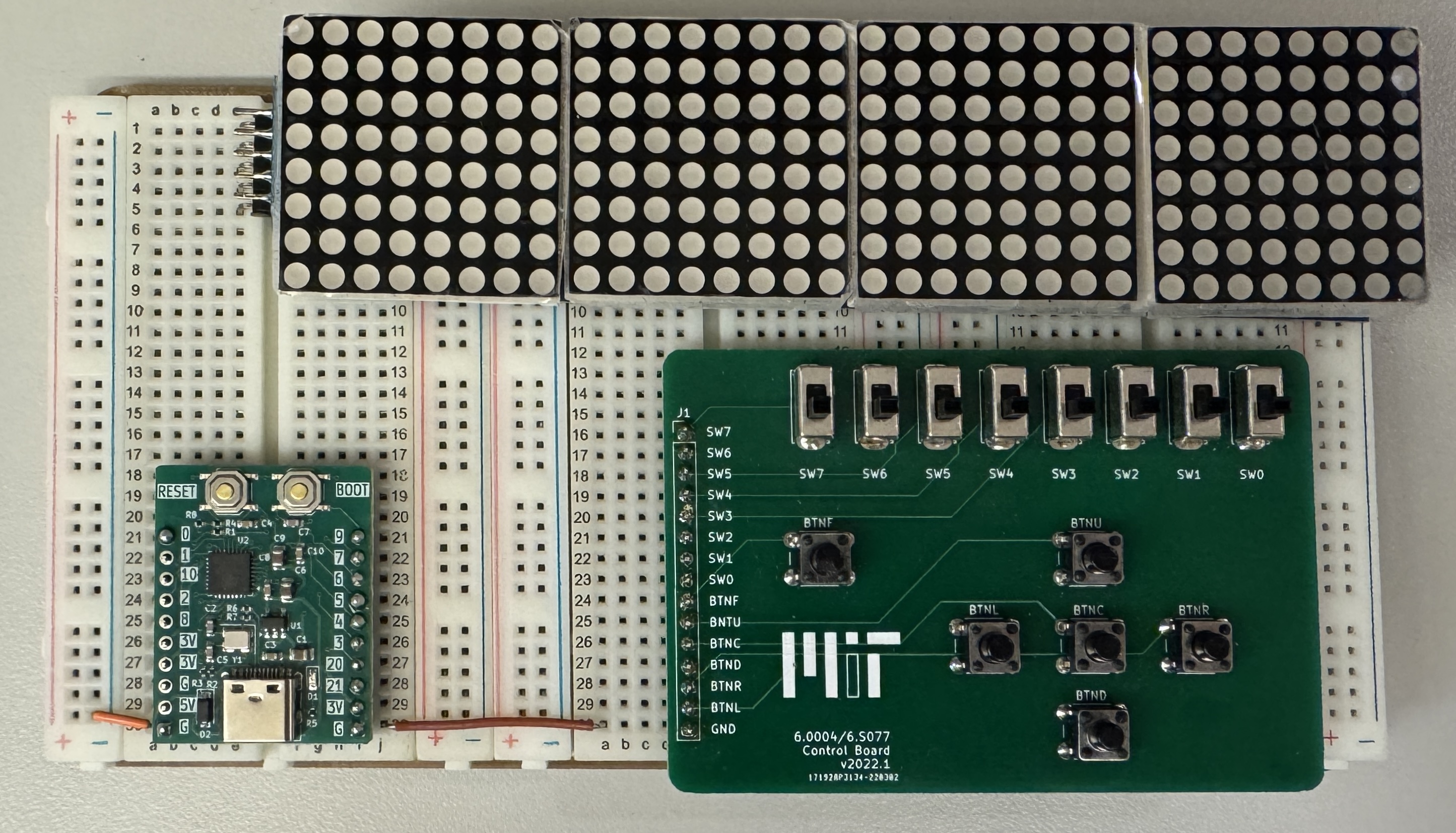
For the postlab, we will use this schematic:

We're just going to connect the ESP32 and the LED array here in lab today.
9.1.1) The Display
Wire up the display using the schematic above. Here's a closer look at what that should look like:
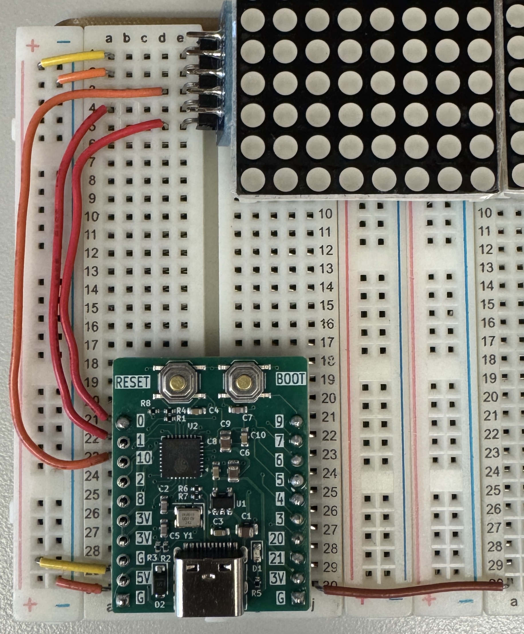
Do not connect any of the switches yet, that will be done later.
Now we should verify that the display is working correctly.
9.2) The Code
9.2.1) Project Creation
Create a new project, just as you did in the setup lab (complete with a src subdirectory).
- Name: 6190_postlab1
9.2.2) Starter Code
Download the starter code for postlab1 here: [Starter Code]. Extract the 6190_postlab1 folder from it and move it into your toplevel 6190 folder. Now navigate your way into the 6190_postlab1 folder.
There is a single file in the src folder inside of 6190_postlab1:
main.c, the main C file.
9.2.3) Header File
In addition, you should copy your 6190.h file from your lab1 project into the src folder in this new project.
Now, since we'll be using a new peripheral device (the LED display) we're going to want to add some more code to this header file.
Copy and paste all of this code to the bottom of your 6190.h file (without overwriting anything... we want it all, including the material you already wrote! Also, notice how it heavily uses your GPIO pin functions?)
/////////////////////////////////////////////////
// Serial Peripheral Interface (SPI) Functions //
/////////////////////////////////////////////////

/* Mapping of GPIO pin to SPI signal */
#define CLK 0
#define CS 1
#define MOSI 10

void spiPause(){
    /* 1 microsecond delay for SPI timing */

    uint64_t t = micros();
    while(micros()-t<1);
}


void spiWrite(uint8_t *data, uint8_t len, uint8_t clk_pin, uint8_t mosi_pin, uint8_t cs_pin ){
    /* Performs software-driven SPI write
     Arguments:
        data: pointer to array of 8-bit values to be sent serially
        len: number of 8-bit values to write
        clk_pin: GPIO pin used to generate clock signal
        mosi_pin: GPIO pin used to transmit data serially
        cs_pin: GPIO pin used for chip select
    */

    pinWrite(cs_pin,0); // bring chip select signal low

    // Send data in buffer in 8-bit chunks
    // Generate clock signal and send 1 bit/clock period
    for (int q=0; q<len; q++){
        for (int p=0; p<8; p++){
            pinWrite(clk_pin,0);
            pinWrite(mosi_pin,((data[q]>>p)&0x01));
            spiPause();
            pinWrite(clk_pin,1);
            spiPause();
        }
    }
    pinWrite(cs_pin,1); // bring chip-select signal high
}

/////////////////
// LED Display //
/////////////////

// LED Display Driver (MAX7219) Documentation: https://datasheets.maximintegrated.com/en/ds/MAX7219-MAX7221.pdf

/* Helper functions for flipping bits */
void bit_reverse(int value, int *dump){
    for (int i = 0; i<32; i++){
        *dump = ((*dump)<<1)|((value>>i)&0x1);
    }
}

uint8_t flip_8(uint8_t value){
    uint8_t t =0;
    for (int i = 0; i<8; i++){
        t = (t<<1)|((value>>i)&0x1);
    }
    return t;
}

/* LED Display Driver Functions */
void setupDisplay(){
    /* Function to set up LED display */

    // Set up necessary GPIO pins
    pinSetup(CS, GPIO_OUTPUT);
    pinSetup(MOSI, GPIO_OUTPUT);
    pinSetup(CLK, GPIO_OUTPUT);

    // Pull chip select, clock, and data out high
    pinWrite(CS,1);
    pinWrite(MOSI,1);
    pinWrite(CLK,1);

    // Configure LED display
    int DISP_TEST = 0x0F000F00; //display test
    int DISP_OFF = 0x0C000C00;  //display off
    int DISP_ON = 0x0C010C01;   //display on
    int DEC_0 = 0x09000900;     //decode mode 0
    int SCAN_M = 0x0B070B07;    //scan mode setting
    int INTENSITY = 0x0A010A01; //screen intensity

    int config_buffers[] = {DISP_TEST, DISP_OFF, DISP_ON, DEC_0, SCAN_M, INTENSITY};

    for (int i = 0; i < 6; i = i + 1){
        int t[2] = {0,0};
        bit_reverse(config_buffers[i],t);
        bit_reverse(config_buffers[i],t+1);
        uint8_t *s = (uint8_t*)t;
        for (int i = 0; i<4; i++){
            spiWrite(s,2,CLK,MOSI,CS);
        }

        int del = millis();
        while(millis()-del<5);
    }
}

uint32_t screen_buffer [8]; // 8x32 array for storing LED display image

void eraseBuffer(){
    /* Function that clears screen buffer by setting all bits to 0. */

    for (uint8_t i=0; i<8; i++){
        screen_buffer[i]=0;     //set all 32 bits to 0
    }
}

void drawBuffer(){
    /* Function that sends bytes in screen buffer to be displayed on LED array.*/

    uint8_t buffer[8];
    for (int k = 1; k <9; k++){
        for (int m=0; m<4;m++){
            buffer[0+2*m] = (uint8_t)flip_8(9-k);
            uint8_t temp = (uint8_t)(screen_buffer[k-1]>>(8*m));
            buffer[1+2*m] = temp & 0x000000FF;
        }
        spiWrite(buffer,8,CLK,MOSI,CS);
    }
}
9.2.4) Moment of Truth
Once you've followed the above instructions (modified the wiring, created the postlab1 project, and updated your 6190.h file), compile your project (don't flash it), and ask for a checkoff. Don't plug in your ESP32 yet. This should only be done DURING your checkoff with staff supervision.
Show your (unplugged) hardware setup to a staff member. Once the staff member is there plug your board back in, compile your project if you have not already, and flash it to your board. If your LED display wiring is correct, you should see a single LED illuminated as shown below:
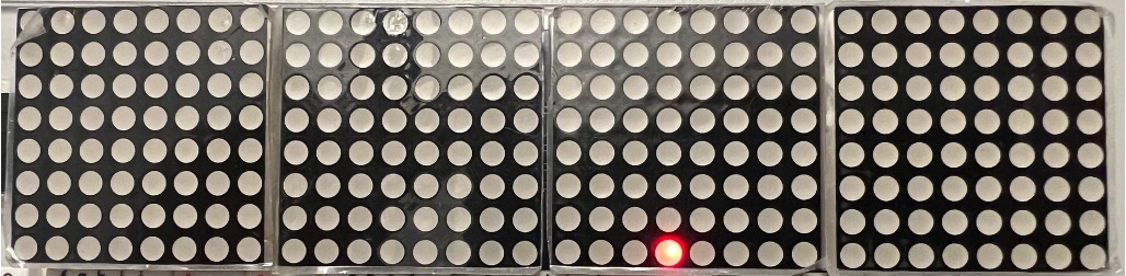
Unplug your USB cable from both the computer and the ESP32, and pack up your kit carefully, keeping everything else assembled.
Footnotes
1the name is coming from rails on railroad tracks.
2and if you've done circuits before and are concerned that we might need a current-limiting resistor for our LED, don't worry, the current is limited by the microcontroller itself here). If you don't know what is being spoken about, don't worry and ignore this footnote.